Protocols
Networking Key Terminology
There are many different terms in the field of information technology. However, we only need to know some of them, only the essential ones. The number of programming languages, functions, protocols, different procedures, areas of application, details, and at the same time, the number of errors that can occur. All these areas are so large that you can specialize your entire career in 1-2 areas.
The key terminology is the rough alphabet we need to know to understand what we will talk about in the other modules. We have created a list with many different but still with the most common protocols and their descriptions to create this foundation. It is important to note that this list is incomplete, and we will cover one or two protocols in other modules. However, we recommend that you review this list from time to time and expand it as you learn new protocols.
| Protocol | Acronym | Description |
|---|---|---|
| Wired Equivalent Privacy | WEP | WEP is a type of security protocol that was commonly used to secure wireless networks. |
| Secure Shell | SSH | A secure network protocol used to log into and execute commands on a remote system |
| File Transfer Protocol | FTP | A network protocol used to transfer files from one system to another |
| Simple Mail Transfer Protocol | SMTP | A protocol used to send and receive emails |
| Hypertext Transfer Protocol | HTTP | A client-server protocol used to send and receive data over the internet |
| Server Message Block | SMB | A protocol used to share files, printers, and other resources in a network |
| Network File System | NFS | A protocol used to access files over a network |
| Simple Network Management Protocol | SNMP | A protocol used to manage network devices |
| Wi-Fi Protected Access | WPA | WPA is a wireless security protocol that uses a password to protect wireless networks from unauthorized access. |
| Temporal Key Integrity Protocol | TKIP | TKIP is also a security protocol used in wireless networks but less secure. |
| Network Time Protocol | NTP | It is used to synchronize the timing of computers on a network. |
| Virtual Local Area Network | VLAN | It is a way to segment a network into multiple logical networks. |
| VLAN Trunking Protocol | VTP | VTP is a Layer 2 protocol that is used to establish and maintain a virtual LAN (VLAN) spanning multiple switches. |
| Routing Information Protocol | RIP | RIP is a distance-vector routing protocol used in local area networks (LANs) and wide area networks (WANs). |
| Open Shortest Path First | OSPF | It is an interior gateway protocol (IGP) for routing traffic within a single Autonomous System (AS) in an Internet Protocol (IP) network. |
| Interior Gateway Routing Protocol | IGRP | IGRP is a Cisco proprietary interior gateway protocol designed for routing within autonomous systems. |
| Enhanced Interior Gateway Routing Protocol | EIGRP | It is an advanced distance-vector routing protocol that is used to route IP traffic within a network. |
| Pretty Good Privacy | PGP | PGP is an encryption program that is used to secure emails, files, and other types of data. |
| Network News Transfer Protocol | NNTP | NNTP is a protocol used for distributing and retrieving messages in newsgroups across the internet. |
| Cisco Discovery Protocol | CDP | It is a proprietary protocol developed by Cisco Systems that allows network administrators to discover and manage Cisco devices connected to the network. |
| Hot Standby Router Protocol | HSRP | HSRP is a protocol used in Cisco routers to provide redundancy in the event of a router or other network device failure. |
| Virtual Router Redundancy Protocol | VRRP | It is a protocol used to provide automatic assignment of available Internet Protocol (IP) routers to participating hosts. |
| Spanning Tree Protocol | STP | STP is a network protocol used to ensure a loop-free topology in Layer 2 Ethernet networks. |
| Terminal Access Controller Access-Control System | TACACS | TACACS is a protocol that provides centralized authentication, authorization, and accounting for network access. |
| Session Initiation Protocol | SIP | It is a signaling protocol used for establishing and terminating real-time voice, video and multimedia sessions over an IP network. |
| Voice Over IP | VOIP | VOIP is a technology that allows for telephone calls to be made over the internet. |
| Extensible Authentication Protocol | EAP | EAP is a framework for authentication that supports multiple authentication methods, such as passwords, digital certificates, one-time passwords, and public-key authentication. |
| Lightweight Extensible Authentication Protocol | LEAP | LEAP is a proprietary wireless authentication protocol developed by Cisco Systems. It is based on the Extensible Authentication Protocol (EAP) used in the Point-to-Point Protocol (PPP). |
| Protected Extensible Authentication Protocol | PEAP | PEAP is a security protocol that provides an encrypted tunnel for wireless networks and other types of networks. |
| Systems Management Server | SMS | SMS is a systems management solution that helps organizations manage their networks, systems, and mobile devices. |
| Microsoft Baseline Security Analyzer | MBSA | It is a free security tool from Microsoft that is used to detect potential security vulnerabilities in Windows computers, networks, and systems. |
| Supervisory Control and Data Acquisition | SCADA | It is a type of industrial control system that is used to monitor and control industrial processes, such as those in manufacturing, power generation, and water and waste treatment. |
| Virtual Private Network | VPN | VPN is a technology that allows users to create a secure, encrypted connection to another network over the internet. |
| Internet Protocol Security | IPsec | IPsec is a protocol used to provide secure, encrypted communication over a network. It is commonly used in VPNs, or Virtual Private Networks, to create a secure tunnel between two devices. |
| Point-to-Point Tunneling Protocol | PPTP | It is a protocol used to create a secure, encrypted tunnel for remote access. |
| Network Address Translation | NAT | NAT is a technology that allows multiple devices on a private network to connect to the internet using a single public IP address. NAT works by translating the private IP addresses of devices on the network into a single public IP address, which is then used to connect to the internet. |
| Carriage Return Line Feed | CRLF | Combines two control characters to indicate the end of a line and a start of a new one for certain text file formats. |
| Asynchronous JavaScript and XML | AJAX | Web development technique that allows creating dynamic web pages using JavaScript and XML/JSON. |
| Internet Server Application Programming Interface | ISAPI | Allows to create performance-oriented web extensions for web servers using a set of APIs. |
| Uniform Resource Identifier | URI | It is a syntax used to identify a resource on the Internet. |
| Uniform Resource Locator | URL | Subset of URI that identifies a web page or another resource on the Internet, including the protocol and the domain name. |
| Internet Key Exchange | IKE | IKE is a protocol used to set up a secure connection between two computers. It is used in virtual private networks (VPNs) to provide authentication and encryption for data transmission, protecting the data from outside eavesdropping and tampering. |
| Generic Routing Encapsulation | GRE | This protocol is used to encapsulate the data being transmitted within the VPN tunnel. |
| Remote Shell | RSH | It is a program under Unix that allows executing commands and programs on a remote computer. |
Common Protocols
Internet protocols are standardized rules and guidelines defined in RFCs that specify how devices on a network should communicate with each other. They ensure that devices on a network can exchange information consistently and reliably, regardless of the hardware and software used. For devices to communicate on a network, they need to be connected through a communication channel, such as a wired or wireless connection. The devices then exchange information using a set of standardized protocols that define the format and structure of the data being transmitted. The two main types of connections used on networks are Transmission Control Protocol (TCP) and User Datagram Protocol (UDP).
We need to deal with and know the different and most used protocols. As we have already learned, these protocols are the basis of all communication between our devices and computers in the networks. We have compiled below many of these protocols that we will be dealing with throughout the modules. The better we understand them, the more effectively we can work with them.
Transmission Control Protocol
TCP is a connection-oriented protocol that establishes a virtual connection between two devices before transmitting data by using a Three-Way-Handshake. This connection is maintained until the data transfer is complete, and the devices can continue to send data back and forth as long as the connection is active.
For example, When we enter a URL into our web browser, the browser sends an HTTP request to the server hosting the website using TCP. The server responds by sending the HTML code for the website back to the browser using TCP. The browser then uses this code to render the website on our screen. This process relies on a TCP connection being established between the browser and the web server and maintained until the data transfer is complete. As a result, TCP is reliable but slower than UDP because it requires additional overhead for establishing and maintaining the connection.
| Protocol | Acronym | Port | Description |
|---|---|---|---|
| Telnet | Telnet | 23 | Remote login service |
| Secure Shell | SSH | 22 | Secure remote login service |
| Simple Network Management Protocol | SNMP | 161-162 | Manage network devices |
| Hyper Text Transfer Protocol | HTTP | 80 | Used to transfer webpages |
| Hyper Text Transfer Protocol Secure | HTTPS | 443 | Used to transfer secure webpages |
| Domain Name System | DNS | 53 | Lookup domain names |
| File Transfer Protocol | FTP | 20-21 | Used to transfer files |
| Trivial File Transfer Protocol | TFTP | 69 | Used to transfer files |
| Network Time Protocol | NTP | 123 | Synchronize computer clocks |
| Simple Mail Transfer Protocol | SMTP | 25 | Used for email transfer |
| Post Office Protocol | POP3 | 110 | Used to retrieve emails |
| Internet Message Access Protocol | IMAP | 143 | Used to access emails |
| Server Message Block | SMB | 445 | Used to transfer files |
| Network File System | NFS | 111, 2049 | Used to mount remote systems |
| Bootstrap Protocol | BOOTP | 67, 68 | Used to bootstrap computers |
| Kerberos | Kerberos | 88 | Used for authentication and authorization |
| Lightweight Directory Access Protocol | LDAP | 389 | Used for directory services |
| Remote Authentication Dial-In User Service | RADIUS | 1812, 1813 | Used for authentication and authorization |
| Dynamic Host Configuration Protocol | DHCP | 67, 68 | Used to configure IP addresses |
| Remote Desktop Protocol | RDP | 3389 | Used for remote desktop access |
| Network News Transfer Protocol | NNTP | 119 | Used to access newsgroups |
| Remote Procedure Call | RPC | 135, 137-139 | Used to call remote procedures |
| Identification Protocol | Ident | 113 | Used to identify user processes |
| Internet Control Message Protocol | ICMP | 0-255 | Used to troubleshoot network issues |
| Internet Group Management Protocol | IGMP | 0-255 | Used for multicasting |
| Oracle DB (Default/Alternative) Listener | oracle-tns | 1521/1526 | The Oracle database default/alternative listener is a service that runs on the database host and receives requests from Oracle clients. |
| Ingres Lock | ingreslock | 1524 | Ingres database is commonly used for large commercial applications and as a backdoor that can execute commands remotely via RPC. |
| Squid Web Proxy | http-proxy | 3128 | Squid web proxy is a caching and forwarding HTTP web proxy used to speed up a web server by caching repeated requests. |
| Secure Copy Protocol | SCP | 22 | Securely copy files between systems |
| Session Initiation Protocol | SIP | 5060 | Used for VoIP sessions |
| Simple Object Access Protocol | SOAP | 80, 443 | Used for web services |
| Secure Socket Layer | SSL | 443 | Securely transfer files |
| TCP Wrappers | TCPW | 113 | Used for access control |
| Internet Security Association and Key Management Protocol | ISAKMP | 500 | Used for VPN connections |
| Microsoft SQL Server | ms-sql-s | 1433 | Used for client connections to the Microsoft SQL Server. |
| Kerberized Internet Negotiation of Keys | KINK | 892 | Used for authentication and authorization |
| Open Shortest Path First | OSPF | 89 | Used for routing |
| Point-to-Point Tunneling Protocol | PPTP | 1723 | Is used to create VPNs |
| Remote Execution | REXEC | 512 | This protocol is used to execute commands on remote computers and send the output of commands back to the local computer. |
| Remote Login | RLOGIN | 513 | This protocol starts an interactive shell session on a remote computer. |
| X Window System | X11 | 6000 | It is a computer software system and network protocol that provides a graphical user interface (GUI) for networked computers. |
| Relational Database Management System | DB2 | 50000 | RDBMS is designed to store, retrieve and manage data in a structured format for enterprise applications such as financial systems, customer relationship management (CRM) systems. |
User Datagram Protocol
On the other hand, UDP is a connectionless protocol, which means it does not establish a virtual connection before transmitting data. Instead, it sends the data packets to the destination without checking to see if they were received.
For example, when we stream or watch a video on a platform like YouTube, the video data is transmitted to our device using UDP. This is because the video can tolerate some data loss, and the transmission speed is more important than the reliability. If a few packets of video data are lost along the way, it will not significantly impact the overall quality of the video. This makes UDP faster than TCP but less reliable because there is no guarantee that the packets will reach their destination.
| Protocol | Acronym | Port | Description |
|---|---|---|---|
| Domain Name System | DNS | 53 | It is a protocol to resolve domain names to IP addresses. |
| Trivial File Transfer Protocol | TFTP | 69 | It is used to transfer files between systems. |
| Network Time Protocol | NTP | 123 | It synchronizes computer clocks in a network. |
| Simple Network Management Protocol | SNMP | 161 | It monitors and manages network devices remotely. |
| Routing Information Protocol | RIP | 520 | It is used to exchange routing information between routers. |
| Internet Key Exchange | IKE | 500 | Internet Key Exchange |
| Bootstrap Protocol | BOOTP | 68 | It is used to bootstrap hosts in a network. |
| Dynamic Host Configuration Protocol | DHCP | 67 | It is used to assign IP addresses to devices in a network dynamically. |
| Telnet | TELNET | 23 | It is a text-based remote access communication protocol. |
| MySQL | MySQL | 3306 | It is an open-source database management system. |
| Terminal Server | TS | 3389 | It is a remote access protocol used for Microsoft Windows Terminal Services by default. |
| NetBIOS Name | netbios-ns | 137 | It is used in Windows operating systems to resolve NetBIOS names to IP addresses on a LAN. |
| Microsoft SQL Server | ms-sql-m | 1434 | Used for the Microsoft SQL Server Browser service. |
| Universal Plug and Play | UPnP | 1900 | It is a protocol for devices to discover each other on the network and communicate. |
| PostgreSQL | PGSQL | 5432 | It is an object-relational database management system. |
| Virtual Network Computing | VNC | 5900 | It is a graphical desktop sharing system. |
| X Window System | X11 | 6000-6063 | It is a computer software system and network protocol that provides GUI on Unix-like systems. |
| Syslog | SYSLOG | 514 | It is a standard protocol to collect and store log messages on a computer system. |
| Internet Relay Chat | IRC | 194 | It is a real-time Internet text messaging (chat) or synchronous communication protocol. |
| OpenPGP | OpenPGP | 11371 | It is a protocol for encrypting and signing data and communications. |
| Internet Protocol Security | IPsec | 500 | IPsec is also a protocol that provides secure, encrypted communication. It is commonly used in VPNs to create a secure tunnel between two devices. |
| Internet Key Exchange | IKE | 11371 | It is a protocol for encrypting and signing data and communications. |
| X Display Manager Control Protocol | XDMCP | 177 | XDMCP is a network protocol that allows a user to remotely log in to a computer running the X11. |
ICMP
Internet Control Message Protocol (ICMP) is a protocol used by devices to communicate with each other on the Internet for various purposes, including error reporting and status information. It sends requests and messages between devices, which can be used to report errors or provide status information.
ICMP Requests
A request is a message sent by one device to another to request information or perform a specific action. An example of a request in ICMP is the ping request, which tests the connectivity between two devices. When one device sends a ping request to another, the second device responds with a ping reply message.
ICMP Messages
A message in ICMP can be either a request or a reply. In addition to ping requests and responses, ICMP supports other types of messages, such as error messages, destination unreachable, and time exceeded messages. These messages are used to communicate various types of information and errors between devices on the network.
For example, if a device tries to send a packet to another device and the packet cannot be delivered, the device can use ICMP to send an error message back to the sender. ICMP has two different versions:
ICMPv4: For IPv4 onlyICMPv6: For IPv6 only
ICMPv4 is the original version of ICMP, developed for use with IPv4. It is still widely used and is the most common version of ICMP. On the other hand, ICMPv6 was developed for IPv6. It includes additional functionality and is designed to address some of the limitations of ICMPv4.
| Request Type | Description |
|---|---|
Echo Request | This message tests whether a device is reachable on the network. When a device sends an echo request, it expects to receive an echo reply message. For example, the tools tracert (Windows) or traceroute (Linux) always send ICMP echo requests. |
Timestamp Request | This message determines the time on a remote device. |
Address Mask Request | This message is used to request the subnet mask of a device. |
| Message Type | Description |
|---|---|
Echo reply | This message is sent in response to an echo request message. |
Destination unreachable | This message is sent when a device cannot deliver a packet to its destination. |
Redirect | A router sends this message to inform a device that it should send its packets to a different router. |
time exceeded | This message is sent when a packet has taken too long to reach its destination. |
Parameter problem | This message is sent when there is a problem with a packet’s header. |
Source quench | This message is sent when a device receives packets too quickly and cannot keep up. It is used to slow down the flow of packets. |
Another crucial part of ICMP for us is the Time-To-Live (TTL) field in the ICMP packet header that limits the packet’s lifetime as it travels through the network. It prevents packets from circulating indefinitely on the network in the event of routing loops. Each time a packet passes through a router, the router decrements the TTL value by 1. When the TTL value reaches 0, the router discards the packet and sends an ICMP Time Exceeded message back to the sender.
We can also use TTL to determine the number of hops a packet has taken and the approximate distance to the destination. For example, if a packet has a TTL of 10 and takes 5 hops to reach its destination, it can be inferred that the destination is approximately 5 hops away. For example, if we see a ping with the TTL value of 122, it could mean that we are dealing with a Windows system (TTL 128 by default) that is 6 hops away.
However, it is also possible to guess the operating system based on the default TTL value used by the device. Each operating system typically has a default TTL value when sending packets. This value is set in the packet’s header and is decremented by 1 each time the packet passes through a router. Therefore, examining a device’s default TTL value makes it possible to infer which operating system the device is using. For example: Windows systems (2000/XP/2003/Vista/10) typically have a default TTL value of 128, while macOS and Linux systems typically have a default TTL value of 64 and Solaris’ default TTL value of 255. However, it is important to note that the user can change these values, so they should be independent of a definitive way to determine a device’s operating system.
VoIP
Voice over Internet Protocol (VoIP) is a method of transmitting voice and multimedia communications. For example, it allows us to make phone calls using a broadband internet connection instead of a traditional phone line, like Skype, Whatsapp, Google Hangouts, Slack, Zoom, and others.
The most common VoIP ports are TCP/5060 and TCP/5061, which are used for the Session Initiation Protocol (SIP). However, the port TCP/1720 may also be used by some VoIP systems for the H.323 protocol, a set of standards for multimedia communication over packet-based networks. Still, SIP is more widely used than H.323 in VoIP systems.
Nevertheless, SIP is a signaling protocol for initiating, maintaining, modifying, and terminating real-time sessions involving video, voice, messaging, and other communications applications and services between two or more endpoints on the Internet. Therefore, it uses requests and methods between the endpoints. The most common SIP requests and methods are:
| Method | Description |
|---|---|
INVITE | Initiates a session or invites another endpoint to participate. |
ACK | Confirms the receipt of an INVITE request. |
BYE | Terminate a session. |
CANCEL | Cancels a pending INVITE request. |
REGISTER | Registers a SIP user agent (UA) with a SIP server. |
OPTIONS | Requests information about the capabilities of a SIP server or user agent, such as the types of media it supports. |
Information Disclosure
However, SIP allows us to enumerate existing users for potential attacks. This can be done for various purposes, such as determining a user’s availability, finding out information about the user’s capabilities or services, or performing brute-force attacks on user accounts later on.
One of the possible ways to enumerate users is the SIP OPTIONS request. It is a method used to request information about the capabilities of a SIP server or user agents, such as the types of media it supports, the codecs it can decode, and other details. The OPTIONS request can probe a SIP server or user agent for information or test its connectivity and availability.
During our analysis, it is possible to discover a SEPxxxx.cnf file, where xxxx is a unique identifier, is a configuration file used by Cisco Unified Communications Manager, formerly known as Cisco CallManager, to define the settings and parameters for a Cisco Unified IP Phone. The file specifies the phone model, firmware version, network settings, and other details.
Wireless Networks
Wireless networks are computer networks that use wireless data connections between network nodes. These networks allow devices such as laptops, smartphones, and tablets to communicate with each other and the Internet without needing physical connections such as cables.
Wireless networks use radio frequency (RF) technology to transmit data between devices. Each device on a wireless network has a wireless adapter that converts data into RF signals and sends them over the air. Other devices on the network receive these signals with their own wireless adapters, and the data is then converted back into a usable form. Those can operate over various ranges, depending on the technology used. For example, a local area network (LAN) that covers a small area, such as a home or small office, might use a wireless technology called WiFi, which has a range of a few hundred feet. On the other hand, a wireless wide area network (WWAN) might use mobile telecommunication technology such as cellular data (3G, 4G LTE, 5G), which can cover a much larger area, such as an entire city or region.
Therefore, to connect to a wireless network, a device must be within range of the network and configured with the correct network settings, such as the network name and password. Once connected, devices can communicate with each other and the Internet, allowing users to access online resources and exchange data.
Communication between devices occurs over RF in the 2.4 GHz or 5 GHz bands in a WiFi network. When a device, like a laptop, wants to send data over the network, it first communicates with the Wireless Access Point (WAP) to request permission to transmit. The WAP is a central device, like a router, that connects the wireless network to a wired network and controls access to the network. Once the WAP grants permission, the transmitting device sends the data as RF signals, which are received by the wireless adapters of other devices on the network. The data is then converted back into a usable form and passed on to the appropriate application or system.
The strength of the RF signal and the distance it can travel are influenced by factors such as the transmitter’s power, the presence of obstacles, and the density of RF noise in the environment. So, to ensure reliable communication, WiFi networks use techniques such as spread spectrum transmission and error correction to overcome these challenges.
WiFi Connection
The device must also be configured with the correct network settings, such as the network name / Service Set Identifier (SSID) and password. So, to connect to the router, the laptop uses a wireless networking protocol called IEEE 802.11. This protocol defines the technical details of how wireless devices communicate with each other and with WAPs. When a device wants to join a WiFi network, it sends a request to the WAP to initiate the connection process. This request is known as a connection request frame or association request and is sent using the IEEE 802.11 wireless networking protocol. The connection request frame contains various fields of information, including the following but not limited to:
MAC address | A unique identifier for the device’s wireless adapter |
|---|---|
SSID | The network name, also known as the Service Set Identifier of the WiFi network |
Supported data rates | A list of the data rates the device can communicate |
Supported channels | A list of the channels (frequencies) on which the device can communicate |
Supported security protocols | |A list of the security protocols that the device is capable of using, such as WPA2/WPA3 |
The device then uses this information to configure its wireless adapter and connect to the WAP. Once the connection is established, the device can communicate with the WAP and other network devices. It can also access the Internet and other online resources through the WAP, which acts as a gateway to the wired network. However, the SSID can be hidden by disabling broadcasting. That means that devices that search for that specific WAP will not be able to identify its SSID. Nevertheless, the SSID can still be found in the authentication packet.
In addition to the IEEE 802.11 protocol, other networking protocols and technologies may also be used, like TCP/IP, DHCP, and WPA2, in a WiFi network to perform tasks such as assigning IP addresses to devices, routing traffic between devices, and providing security.
WEP Challenge-Response Handshake
The challenge-response handshake is a process to establish a secure connection between a WAP and a client device in a wireless network that uses the WEP security protocol. This involves exchanging packets between the WAP and the client device to authenticate the device and establish a secure connection.
| Step | Who | Description |
|---|---|---|
| 1 | Client | Sends an association request packet to the WAP, requesting access. |
| 2 | WAP | Responds with an association response packet to the client, which includes a challenge string. |
| 3 | Client | Calculates a response to the challenge string and a shared secret key and sends it back to the WAP. |
| 4 | WAP | Calculates the expected response to the challenge with the same shared secret key and sends an authentication response packet to the client. |
Nevertheless, some packets can get lost, so the so-called CRC checksum has been integrated. Cyclic Redundancy Check (CRC) is an error-detection mechanism used in the WEP protocol to protect against data corruption in wireless communications. A CRC value is calculated for each packet transmitted over the wireless network based on the packet’s data. It is used to verify the integrity of the data. When the destination device receives the packet, the CRC value is recalculated and compared to the original value. If the values match, the data has been transmitted successfully without any errors. However, if the values do not match, the data has been corrupted and needs to be retransmitted.
The design of the CRC mechanism has a flaw that allows us to decrypt a single packet without knowing the encryption key. This is because the CRC value is calculated using the plaintext data in the packet rather than the encrypted data. In WEP, the CRC value is included in the packet header along with the encrypted data. When the destination device receives the packet, the CRC value is recalculated and compared to the original one to ensure that the data has been transmitted successfully without any errors. However, we can use the CRC to determine the plaintext data in the packet, even if the data is encrypted.
Security Features
WiFi networks have several security features to protect against unauthorized access and ensure the privacy and integrity of data transmitted over the network. Some of the leading security features include but are not limited to:
- Encryption
- Access Control
- Firewall
Encryption
We can use various encryption algorithms to protect the confidentiality of data transmitted over wireless networks. The most common encryption algorithms in WiFi networks are Wired Equivalent Privacy (WEP), WiFi Protected Access 2 (WPA2), and WiFi Protected Access 3 (WPA3).
Access Control
WiFi networks are configured by default to allow authorized devices to join the network using specific authentication methods. However, these methods can be changed by requiring a password or a unique identifier (such as a MAC address) to identify authorized devices.
Firewall
A firewall is a security system that controls incoming and outgoing network traffic based on predetermined security rules. For example, WiFi routers often have built-in firewalls that can block incoming traffic from the Internet and protect against various types of cyber threats.
Encryption Protocols
Wired Equivalent Privacy (WEP) and WiFi Protected Access (WPA) are encryption protocols that secure data transmitted over a WiFi network. WPA can use different encryption algorithms, including Advanced Encryption Standard (AES).
WEP
WEP uses a 40-bit or 104-bit key to encrypt data, while WPA using AES uses a 128-bit key. Longer keys provide more robust encryption and are more resistant to attacks. However, it is vulnerable to various attacks that can allow an attacker to decrypt data transmitted over the network. In addition, WEP is not compatible with newer devices and operating systems and is generally no longer considered secure. Finally, WEP uses the RC4 cipher encryption algorithm, which makes it vulnerable to attacks.
However, WEP uses a shared key for authentication, which means the same key is used for encryption and authentication. There are two versions of the WEP protocol:
WEP-40/WEP-64WEP-104
WEP-40, also known as WEP-64, uses a 40-bit (secret) key, while WEP-104 uses a 104-bit key. The key is divided into an Initialization Vector (IV) and a secret key.
The IV is a small value included in the packet header along with the encrypted data and is used to create the key for both WEP-40 and WEP-104 and is included to ensure that each key is unique. The secret key is a series of random bits used to encrypt the data. However, the WEP-104 has a 80-bits long secret key. Let us look at the following table to see the differences clearly:
| Protocol | IV | Secret Key |
|---|---|---|
WEP-40/WEP-64 | 24-bit | 40-bit |
WEP-104 | 24-bit | 80-bit |
However, since the IV in WEP is relatively small, we can brute force it, try every possible combination of characters for it, and determine the correct value. Afterward, we can use it to decrypt the data in the packet. This allows us to access the data transmitted over the wireless network and potentially compromise the network’s security.
WPA
WPA provides the highest level of security and is not susceptible to the same types of attacks as WEP. In addition, WPA uses more secure authentication methods, such as a Pre-Shared Key (PSK) or an 802.1X authentication server, which provide stronger protection against unauthorized access. Although older devices may not support WPA is compatible with most devices and operating systems. All wireless networks, especially in critical infrastructure like offices, should generally implement at least WPA2 or even WPA3 encryption.
Authentication Protocols
Lightweight Extensible Authentication Protocol (LEAP) and Protected Extensible Authentication Protocol (PEAP) are authentication protocols used to secure wireless networks to provide a secure method for authenticating devices on a wireless network and are often used in conjunction with WEP or WPA to provide an additional layer of security.
LEAP and PEAP are both based on the Extensible Authentication Protocol (EAP), a framework for authentication used in various networking contexts. However, one key difference between LEAP and PEAP is how they secure the authentication process.
LEAPuses ashared keyfor authentication, which means that thesame keyis used forencryption and authentication.
This can make it relatively easy for us to gain access to the network if the key is compromised.
However, PEAP uses a more secure authentication method called tunneled Transport Layer Security (TLS). This method establishes a secure connection between the device and the WAP using a digital certificate, and an encrypted tunnel protects the authentication process. This provides more robust protection against unauthorized access and is more resistant to attacks.
TACACS+
In a wireless network, when a wireless access point (WAP) sends an authentication request to a Terminal Access Controller Access-Control System Plus (TACACS+) server, it is likely that the entire request packet will be encrypted to protect the confidentiality and integrity of the request.
TACACS+ is a protocol used to authenticate and authorize users accessing network devices, such as routers and switches. When a WAP sends an authentication request to a TACACS+ server, the request typically includes the user’s credentials and other information about the session.
Encrypting the authentication request helps to ensure that this sensitive information is not visible to unauthorized parties who may be able to intercept the request. At the same time, it is being transmitted over the network. It also helps prevent tampering with the request or replacing it with a malicious request of their own.
Several encryption methods may be used to encrypt the authentication request, such as SSL/TLS or IPSec. The specific encryption method used may depend on the configuration of the TACACS+ server and the capabilities of the WAP.
Disassociation Attack
A Disassociation Attack is a type of all wireless network attack that aims to disrupt the communication between a WAP and its clients by sending disassociation frames to one or more clients.
The WAP uses disassociation frames to disconnect a client from the network. When a WAP sends a disassociation frame to a client, the client will disconnect from the network and have to reconnect to continue using the network.
We can launch the attack from within or outside the network depending on our location and network security measures. The purpose of this attack is to disrupt the communication between the WAP and its clients, causing the clients to disconnect and possibly causing inconvenience or disruption to the users. We can also use it as a precursor to other attacks, such as a MITM attack, by forcing the clients to reconnect to the network and potentially exposing them to further attacks.
Wireless Hardening
There are many different ways to protect wireless networks. However, some examples should be considered to increase wireless networks’ security dramatically. These are the following, but not limited to:
- Disabling broadcasting
- WiFi Protected Access
- MAC filtering
- Deploying EAP-TLS
Disabling Broadcasting
Disabling the broadcasting of the SSID is a security measure that can help harden a WAP by making it more difficult to discover and connect to the network. When the SSID is broadcasted, it is included in beacon frames regularly transmitted by the WAP to advertise the availability of the network. By disabling the broadcasting of the SSID, the WAP will not transmit beacon frames, and the network will not be visible to devices that are not already connected to the network.
WPA
Again, WPA provides strong encryption and authentication for wireless communications, helping protect against unauthorized network access and sensitive data interception. WPA includes two main versions:
- WPA-Personal
- WPA-Enterprise
WPA-Personal, designed for home and small business networks, and WPA-Enterprise, designed for larger organizations and uses a centralized authentication server (e.g., RADIUS or TACACS+) to verify the identity of clients.
MAC Filtering
MAC filtering is a security measure that allows a WAP to accept or reject connections from specific devices based on their MAC addresses. By configuring the WAP to accept connections only from devices with approved MAC addresses, it is possible to prevent unauthorized devices from connecting to the network.
Deploying EAP-TLS
EAP-TLS is a security protocol used to authenticate and encrypt wireless communications. It uses digital certificates and PKI to verify the identity of clients and establish secure connections. Deploying EAP-TLS can help to harden a WAP by providing strong authentication and encryption for wireless communications, which can protect against unauthorized access to the network and the interception of sensitive data.
Virtual Private Networks (VPN)
A Virtual Private Network (VPN) is a technology that allows a secure and encrypted connection between a private network and a remote device. This allows the remote machine to access the private network directly, providing secure and confidential access to the network’s resources and services. For example, an administrator from another location has to manage the internal servers so that the employees can continue to use the internal services. Many companies limit servers’ access, so clients can only reach those servers from the local network. This is where VPN comes into play, where the administrator connects to the VPN server via the internet, authenticates himself, and thus creates an encrypted tunnel so that others cannot read the data transfer. In addition, the administrator’s computer is also assigned a local (internal) IP address through which he can access and manage the internal servers. Administrators commonly use VPNs to provide secure and cost-effective remote access to a company’s network. VPN typically uses the ports TCP/1723 for Point-to-Point Tunneling Protocol PPTP VPN connections and UDP/500 for IKEv1 and IKEv2 VPN connections.
This allows employees to access the network and its resources, such as email and file servers, from remote locations, such as their homes or while traveling. There are several reasons why administrators use VPNs. VPNs encrypt the connection between the remote device and the private network, making it much more difficult for attackers to intercept and steal sensitive information. With this, the entire communication is more secure.
Another reason is that VPNs allow employees to access the private network and its resources remotely from anywhere, as long as they have an internet connection. This is particularly useful for employees who need to work remotely, such as those traveling or working from home. Additionally, VPNs can be more cost-effective than other remote access solutions, such as leased lines or dedicated connections, because they use the public internet to connect remote users to the private network.
Moreover, we can use VPNs to connect multiple remote locations, such as branch offices, into a single private network, making it easier to manage and access network resources. However, several components and requirements are necessary for a VPN to work:
| Requirement | Description |
|---|---|
VPN Client | This is installed on the remote device and is used to establish and maintain a VPN connection with the VPN server. For example, this could be an OpenVPN client. |
VPN Server | This is a computer or network device responsible for accepting VPN connections from VPN clients and routing traffic between the VPN clients and the private network. |
Encryption | VPN connections are encrypted using a variety of encryption algorithms and protocols, such as AES and IPsec, to secure the connection and protect the transmitted data. |
Authentication | The VPN server and client must authenticate each other using a shared secret, certificate, or another authentication method to establish a secure connection. |
The VPN client and server use these ports to establish and maintain the VPN connection. At the TCP/IP layer, a VPN connection typically uses the Encapsulating Security Payload (ESP) protocol to encrypt and authenticate the VPN traffic. This allows the VPN client and server to exchange data over the public internet securely.
IPsec
Internet Protocol Security (IPsec) is a network security protocol that provides encryption and authentication for internet communications. It is a powerful and widely-used security protocol that provides encryption and authentication for internet communications and works by encrypting the data payload of each IP packet and adding an authentication header (AH), which is used to verify the integrity and authenticity of the packet. IPsec uses a combination of two protocols to provide encryption and authentication:
-
Authentication Header (
AH): This protocol provides integrity and authenticity for IP packets but does not provide encryption. It adds an authentication header to each IP packet, which contains a cryptographic checksum that can be used to verify that the packet has not been tampered with. -
Encapsulating Security Payload (
ESP): This protocol provides encryption and optional authentication for IP packets. It encrypts the data payload of each IP packet and optionally adds an authentication header, similar to AH.
IPsec can be used in two modes.
| Mode | Description |
|---|---|
Transport Mode | In this mode, IPsec encrypts and authenticates the data payload of each IP packet but does not encrypt the IP header. This is typically used to secure end-to-end communication between two hosts. |
Tunnel Mode | With this mode, IPsec encrypts and authenticates the entire IP packet, including the IP header. This is typically used to create a VPN tunnel between two networks. |
For example, an administrator could place a firewall in between. In order to facilitate IPsec VPN traffic from a VPN client outside a firewall to a VPN server inside, the firewall would need to allow the following protocols:
| Protocol | Port | Description |
|---|---|---|
Internet Protocol (IP) | UDP/50-51 | This is the primary protocol that provides the foundation for all internet communication. It is used to route packets of data between the VPN client and the VPN server. |
Internet Key Exchange (IKE) | UDP/500 | IKE is a protocol that is used to establish and maintain secure communication between the VPN client and the VPN server. It is based on the Diffie-Hellman key exchange algorithm, and it is used to negotiate and establish shared secret keys that can be used to encrypt and decrypt the VPN traffic. |
Encapsulating Security Payload (ESP) | UDP/4500 | ESP is also a protocol that provides encryption and authentication for IP datagrams. It is used to encrypt the VPN traffic between the VPN client and the VPN server, using the keys that were negotiated with IKE. |
These protocols are necessary for facilitating IPsec VPN traffic because they provide the security and encryption that are required for secure communication over the public internet. Without these protocols, the VPN traffic would be vulnerable to interception and tampering.
PPTP
Point-to-Point Tunneling Protocol (PPTP) is a network protocol that enables the creation of VPNs by establishing a secure tunnel between the VPN client and server, encapsulating the data transmitted within this tunnel. Originally an extension of the Point-to-Point Protocol (PPP), PPTP is supported by many operating systems.
However, due to its known vulnerabilities, PPTP is no longer considered secure. It can tunnel protocols such as IP, IPX, or NetBEUI via IP, but has been largely replaced by more secure VPN protocols like L2TP/IPsec, IPsec/IKEv2, and OpenVPN. Since 2012, the use of PPTP has declined because its authentication method, MSCHAPv2, employs the outdated DES encryption, which can be easily cracked with specialized hardware.
Vendor Specific Information
Cisco IOS is the operating system of Cisco network devices such as routers and switches. It provides features and services required to manage and operate network devices. This operating system comes in different versions and releases that vary in features, support, and performance. It offers several features required for the operation of modern networks, such as, but not limited to:
- Support for IPv6
- Quality of Service (QoS)
- Security features such as encryption and authentication
- Virtualization features such as Virtual Private LAN Service (VPLS)
- Virtual Routing and Forwarding (VRF)
Cisco IOS can be managed in several ways, depending on the network device and hardware used. The most commonly used method is the command line interface (CLI), which can also be managed in the graphical user interface (GUI). In addition, it supports various network protocols and services required for network operations. These include:
| Protocol Type | Description |
|---|---|
Routing protocols | Such as OSPF and BGP are used to route data packets on a network. |
Switching protocols | Such as VLAN Trunking Protocol (VTP) and Spanning Tree Protocol (STP) is used to configure and manage switches on a network. |
Network services | Such as Dynamic Host Configuration Protocol (DHCP) are used to automatically provide clients on the network with IP addresses and other network configurations. |
Security features | Such as Access Control Lists (ACLs), which are used to control access to network resources and prevent security threats. |
In Cisco IOS, different types of passwords are used for various purposes, for example:
| Password Type | Description |
|---|---|
User | The user password is used for logging in to Cisco IOS. It is used to restrict access to the network device and its features. |
Enable Password | The enable password is used to enter “enable” mode. The “enable” mode is the mode where you have access to advanced functions and settings. |
Secret | The secret is a password to secure access to certain functions and services. It is often used to restrict access to remote management tools and services. |
Enable Secret | The enable secret is an extra-secure password used to secure access to “enable” mode, and they are stored encrypted to provide additional protection. |
We highly recommend going through the provided external resources to understand the encryption mechanics of Cisco IOS and how those are used.
The Cisco IOS devices can be configured for SSH or Telnet. So it can be accessed remotely. We can determine from the response we receive that it is indeed a Cisco IOS, as it responds with the User Access Verification message.
Cisco IOS
Vendor Specific Information
VOIDstrike@htb[/htb]$ telnet 10.129.10.2

Trying 10.129.10.2...
Connected to 10.129.10.2.
Escape character is '^]'.


User Access Verification

Password:
VLANs
Imagine this scenario: A startup called XQ hired a network administrator to create a network for their single-office company, and due to budget limitations, they can only afford one switch and router. The sysadmin of XQ stated that in addition to hosting the web and database servers in the network, staff from different departments will be using it. As a seasoned network security specialist, the network administrator immediately thought about the security attacks that an insider can perform, especially ones abusing broadcast traffic, such as broadcast storms. Therefore, to tackle this problem, the network administrator decided to logically segment the network with Virtual Local Area Networks (VLANS), conceptually breaking down one switch into smaller mini-switches.
A VLAN is a logical grouping of network endpoints connected to defined ports on a switch, allowing the segmentation of networks by creating logical broadcast domains that can span multiple physical LAN segments. With VLANs, network administrators can segment networks based on factors such as team, function, department, or application, without worrying about the physical location of endpoints and users. A broadcast packet sent over one VLAN does not reach any other endpoint that is a member of another VLAN. Because each VLAN is regarded as a broadcast domain, it needs to have its own subnet; for example, the network administrator contracted by XQ can segment the network by departments:
| Department | VLAN ID | Subnet |
|---|---|---|
Servers | VLAN 10 | 192.168.1.0/24 |
C-Level | VLAN 20 | 192.168.2.0/24 |
Finance | VLAN 30 | 192.168.3.0/24 |
HR | VLAN 40 | 192.168.4.0/24 |
Marketing | VLAN 50 | 192.168.5.0/24 |
Support | VLAN 60 | 192.168.6.0/24 |
A myriad of benefits is attained when using VLANs, including:
Better Organization: Network administrators can group endpoints based on any common attribute they share.Increased Security: Network segmentation disallows unauthorized members from sniffing network packets in otherVLANs.Simplified Administration: Network administrators do not have to worry about the physical locations of an endpoint.Increased Performance: With reduced broadcast traffic for all endpoints, more bandwidth is made available for use by the network.
Cisco switches provide the VLAN IDs/numbers 1-4094 (0 and 4095 are reserved IDs and cannot be used); IDs 1-1005 (VLAN 1 is known as the default VLAN and cannot/should not be altered nor deleted) are known as normal-range VLANs, with IDs 1002-1005 being reserved for Token Ring and Fiber Distributed Data Interface (FDDI) VLANs, while IDs 1006-4094 are known as extended-range VLANs. By default, any customization applied for normal-range VLANs is saved in the VLAN database (the vlan.dat file), in contrast to extended-range VLANs, which do not have their customizations saved. VLANs 2-1001 stored in vlan.dat can have parameters including name, type, state, and maximum transmission unit (MTU).
VLAN Memberships
Network administrators can assign the ports of a switch to VLANs either statically or dynamically. Static VLAN assignment, which is the simplest and most common method, involves assigning each port to a VLAN manually using the switch’s network operating system; this must be done for all switches separately (it is essential to keep in mind that endpoints connecting to these ports are unaware of the existence of VLANs). In contrast, dynamic VLAN assignment automatically determines an endpoint’s VLAN membership based on MAC addresses or protocols. The system administrator can register the MAC addresses in a centralized VLAN management service/database, such as the VLAN Membership Policy Server (VMPS) service, and then the switch queries the database of VMPS to determine the VLAN of the endpoint with that specific MAC address. Regardless of their flexibility and mobility, dynamic VLANs increase administrative overhead.
Security-wise, static VLANs are the more secure option because a port will forever be tied to a specific VLAN ID, unless changed manually afterward. For dynamic VLANs, an attacker could potentially utilize tools such as macchanger to spoof the MAC address of legitimate endpoints and attain membership of their VLANs, therefore sniffing all network traffic sent through them.
Access and Trunk Ports
Any port on a VLAN-enabled switch must be either an access port or a trunk port. Access ports belong to and can carry the traffic of only one VLAN (or in some cases two, with the second being for voice traffic); any traffic arriving on an access port is assumed to belong to the VLAN the port was assigned. On the other hand, trunk ports can carry multiple VLANs at the same time; trunk links connect two trunk ports on two switches (or a switch and router) to allow information from multiple VLANs to be carried out across switches.
VLAN Identification
Standard 802.3 Ethernet frames do not contain VLAN information; therefore, switches and other VLAN-enabled devices need a mechanism to keep track of all the VLAN information associated with a packet while traversing VLAN-enabled devices. Two main trunking methods are utilized to achieve this, ISL and IEEE 802.1Q.
Inter-Switch Link (ISL)
Inter-Switch Link (ISL) is a Cisco-proprietary protocol used for trunking between VLAN-enabled devices. Although ISL is one of the first trunking methods (predating 802.1Q), it is deprecated and not as widely used in modern Cisco switches (and routers). Instead, most only support the widely adopted 802.1Q. ISL encapsulated the entire Ethernet frame, including the original Ethernet header and the VLAN tag, adding its 26-byte header and 4-byte trailer.
IEEE 802.1Q
To ensure interoperability of VLAN technologies from the various network-equipments vendors, the Institute of Electrical and Electronics Engineers (IEEE) developed the 802.1Q specification in 1998. The IEEE 802 committee had to change the 802.3 Ethernet frame format by adding a pair of 2-byte fields, TPID and TCI (which consists of three subfields, PCP, DEI, and VID), resulting in a VLAN-compliant 802.1Q Ethernet frame.
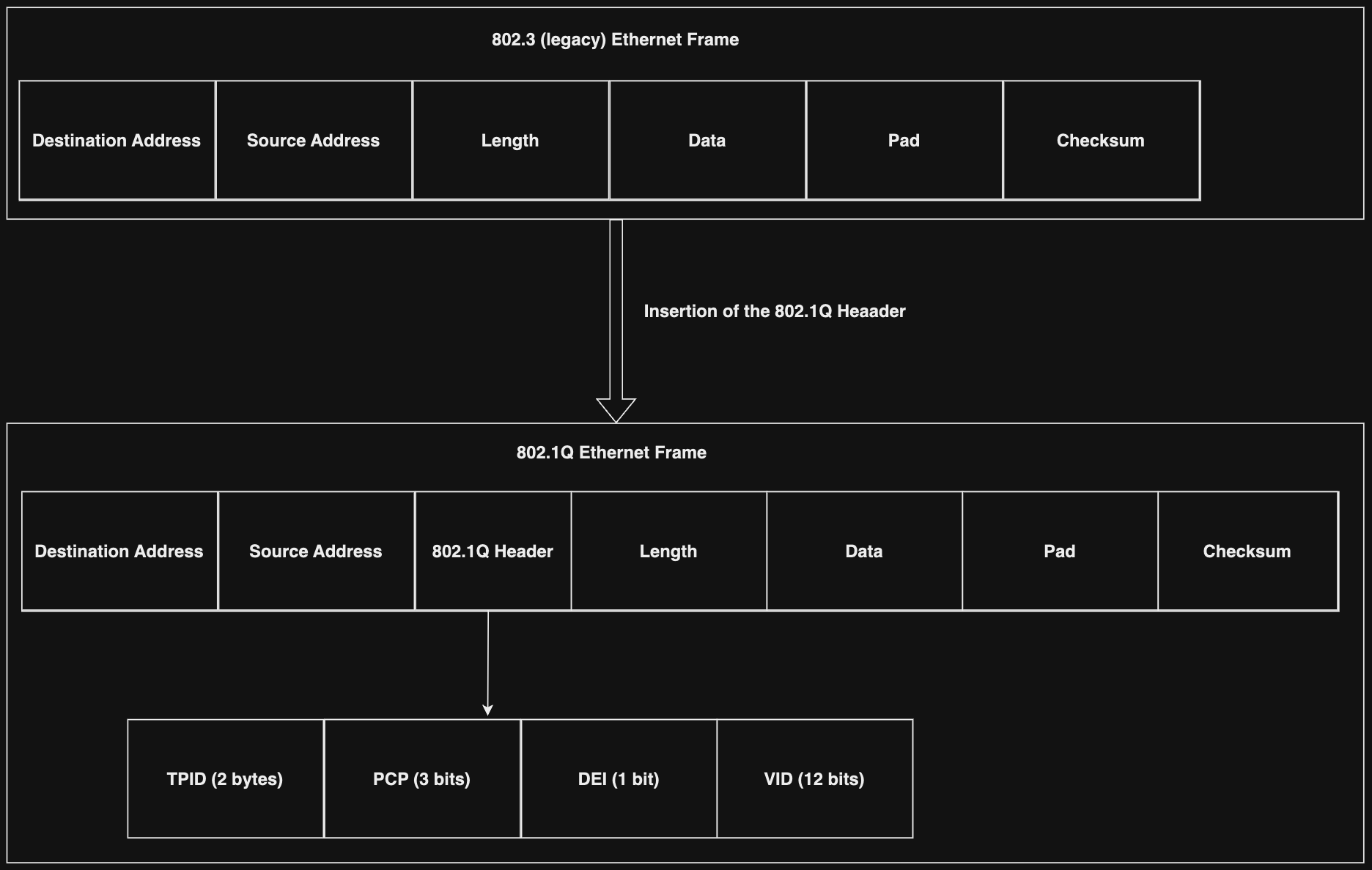
Tag protocol identifier (TPID) is a 16-bit field always set to 0x8100 to identify the Ethernet frame as an 802.1Q-tagged frame. Tag Control Information (TCI) is a 16-bit field containing Priority code point (PCP), Drop eligible indicator (DEI) (previously known as Canonical format indicator (CFI)), and VLAN identifier (VID). The main field concerning VLANs is VID, occupying the low-order 12-bits of TCI. Since it is 12 bits, it allows 2^12 - 2 = 4096 (remember, 0 and 4095 are reserved) VLAN IDs. Therefore, an 802.1Q-tagged frame can contain information for 4094 VLANs; the practice of inserting multiple 802.1Q tags within a single packet is known as Double Tagging, introduced by 802.1ad. VLAN tagging is the process of inserting VLAN information into an 802.1Q Ethernet header, while VLAN untagging is the process of removing the VLAN information from an 802.1Q-tagged Ethernet frame and forwarding the packet to the destined ports.
VLAN-Capable NICs
Some network interface cards (NICs) attached to computers/servers support VLAN tagging. Let us see how we can assign a VLAN ID to a NIC using Linux and Windows.
Assigning NICs a VLAN in Linux
In Linux, creating a VLAN is done by creating an interface on top of another, called a parent interface. This VLAN interface will tag packets with the assigned VLAN ID while returning packets will be untagged.
To assign a network adapter a VLAN in Linux, many tools can be used, such as ip, nmcli, and vconfig (deprecated). However, first, we need to ensure that the Kernel has the 802.1Q module loaded:
VLANs
VOIDstrike@htb[/htb]$ sudo modprobe 8021qSubsequently, we can use lsmod to make sure 8021q was loaded successfully:
VLANs
VOIDstrike@htb[/htb]$ lsmod | grep 8021

8021q                  40960  0
garp                   16384  1 8021q
mrp                    20480  1 8021q
Now, we need to find the name of the physical Ethernet interface that we will create the VLAN interface on top of, which is eth0:
VLANs
VOIDstrike@htb[/htb]$ ip a

<SNIP>
2: eth0: <BROADCAST,MULTICAST,UP,LOWER_UP> mtu 1500 qdisc fq_codel state UP group default qlen 1000
    link/ether a6:ba:3b:08:3a:36 brd ff:ff:ff:ff:ff:ff
    altname enp0s3
    altname ens3
    inet 94.2X.5X.72/22 brd 94.237.51.255 scope global dynamic eth0
       valid_lft 83489sec preferred_lft 83489sec
    inet6 fe80::a4ba:3bff:fe08:3a36/64 scope link
       valid_lft forever preferred_lft forever
Then, we will use vconfig to create a new interface that is a member of the desired VLAN, 20, for example, on top of eth0:
VLANs
VOIDstrike@htb[/htb]$ sudo vconfig add eth0 20

Warning: vconfig is deprecated and might be removed in the future, please migrate to ip(route2) as soon as possible!
To use ip instead:
VLANs
sudo ip link add link eth0 name eth0.20 type vlan id 20Either of these commands will make a new interface called eth0.20@eth0:
VLANs
VOIDstrike@htb[/htb]$ ip a

<SNIP>
4: eth0.20@eth0: <BROADCAST,MULTICAST> mtu 1500 qdisc noop state DOWN group default qlen 1000
    link/ether a6:ba:3b:08:3a:36 brd ff:ff:ff:ff:ff:ff
Then, based on the subnet assigned to the addresses with VLAN 20 within the local network, we need to assign the interface an IP address and then start it:
VLANs
VOIDstrike@htb[/htb]$ sudo ip addr add 192.168.1.1/24 dev eth0.20
VOIDstrike@htb[/htb]$ sudo ip link set up eth0.20
At last, we can check whether the interface has changed states to up:
VLANs
VOIDstrike@htb[/htb]$ ip a | grep eth0.20

4: eth0.20@eth0: <BROADCAST,MULTICAST,UP,LOWER_UP> mtu 1500 qdisc noqueue state UP group default qlen 1000
    inet 192.168.1.1/24 scope global eth0.20
Assigning NICs a VLAN in Windows
On Windows, to assign a VLAN for a physical network adapter that supports VLAN tagging, first we need to open Device Manager:
Then we need to click on Properties for the Ethernet interface we want to assign to a VLAN:
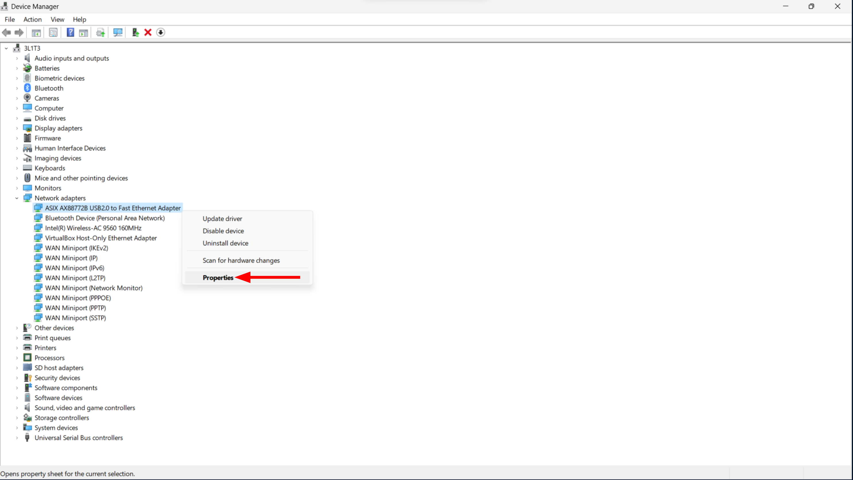
Within Advanced, there will be a VLAN ID property to which we can assign a value. After clicking OK, if the adapter supports assigning a VLAN, it will be set; otherwise, the window will close, and no VLAN tag will be added to any packets originating from this host:

Instead of relying on the GUI, we can use PowerShell. First, let us get the names of all the available physical network adapters using the Get-NetAdapter Cmdlet:
VLANs
PS C:\> Get-NetAdapter | Format-Table -AutoSize

Name                                           InterfaceDescription                                                          ifIndex Status             MacAddress              LinkSpeed
----                                           --------------------                                                          ------- ------             ----------              ---------
VirtualBox Host-Only Network  VirtualBox Host-Only Ethernet Adapter                                        20 Up                    0A-00-27-10-42-15       1 Gbps
Ethernet 2                                 ASIX AX88772B USB2.0 to Fast Ethernet Adapter                            55 Up                    90-EB-78-14-21-7F    100 Mbps
Bluetooth Network Connection  Bluetooth Device (Personal Area Network)                                   18 Disconnected   38-41-25-E8-DE-2D        3 Mbps
Wi-Fi                                         Intel(R) Wireless-AC 9560 160MHz                                                12 Disconnected   8E-36-6A-7A-BA-6A 866.7 Mbps
Previously, we used Device Manager to assign Ethernet 2 to VLAN 10; to retrieve the VLAN ID of the interface, we can use the Get-NetAdapaterAdvancedProperty Cmdlet with the -DisplayName flag along with vlan id:
VLANs
PS C:\> Get-NetAdapterAdvancedProperty -DisplayName "vlan id"

Name                      DisplayName                    DisplayValue                   RegistryKeyword RegistryValue
----                      -----------                    ------------                   --------------- -------------
Ethernet 2                VLAN ID                        10                                     VLAN_ID               {10}
We can also set the VLAN ID of a physical network address using the Set-NetAdapter Cmdlet along with the VlanID flag; this powerful Cmdlet can also be used to customize other properties of interfaces such as MAC addresses:
VLANs
PS C:\> Set-NetAdapter -Name "Ethernet 2" -VlanID 10However, remember that this operation only succeeds if the network interface supports this functionality; otherwise, PowerShell will throw an error indicating that the interface does not support it.
Analyzing VLAN Tagged Traffic
We can identify and analyze VLAN tagged traffic on a network with Wireshark using the vlan filter. For example, when analyzing a network packet dump, we can inspect packets with 802.1Q tagging using the filter vlan:
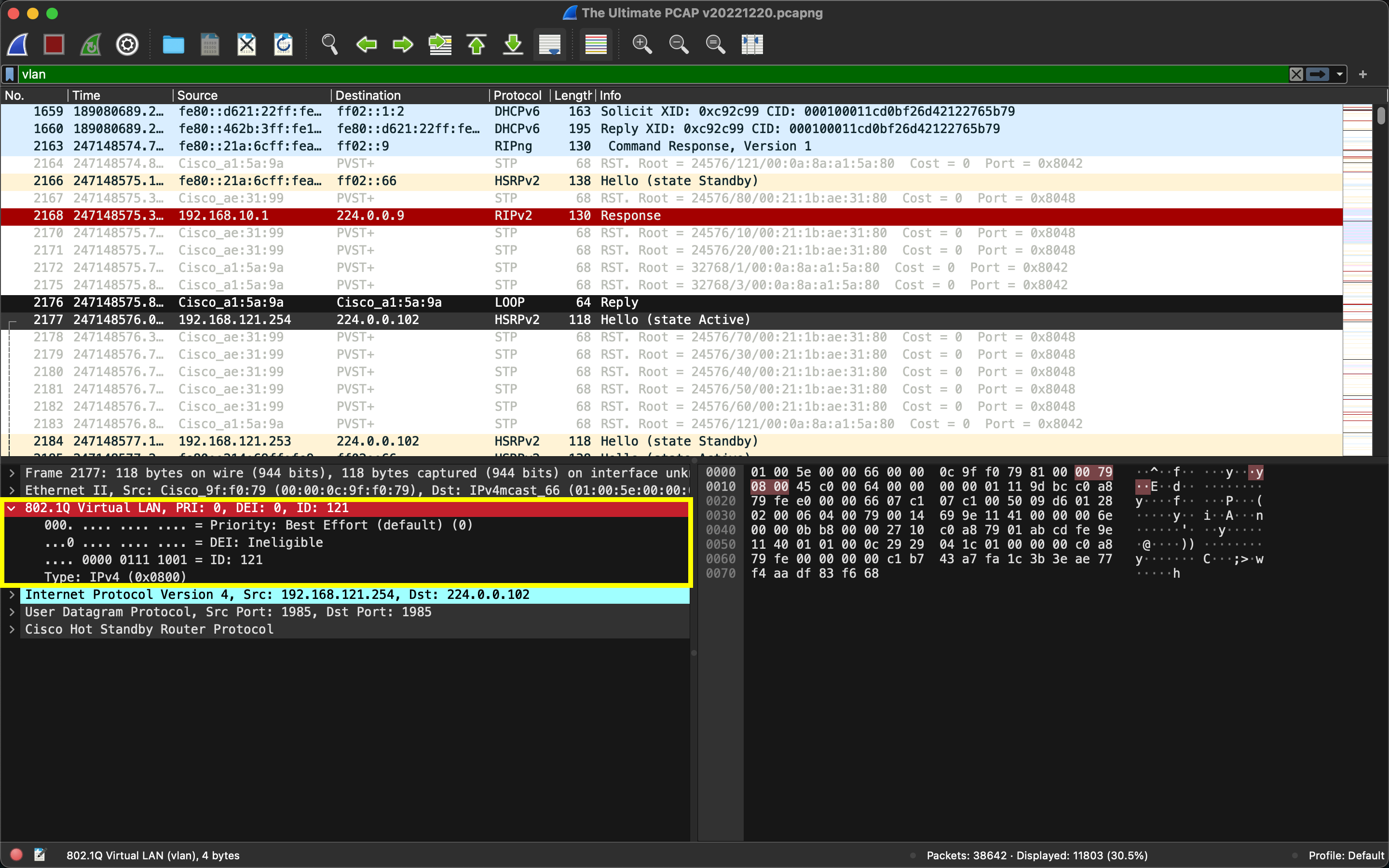
Moreover, we can search for packets with a specific VLAN ID; for example, to search for packets having VLAN 10, we can use the filter vlan.id == 10:
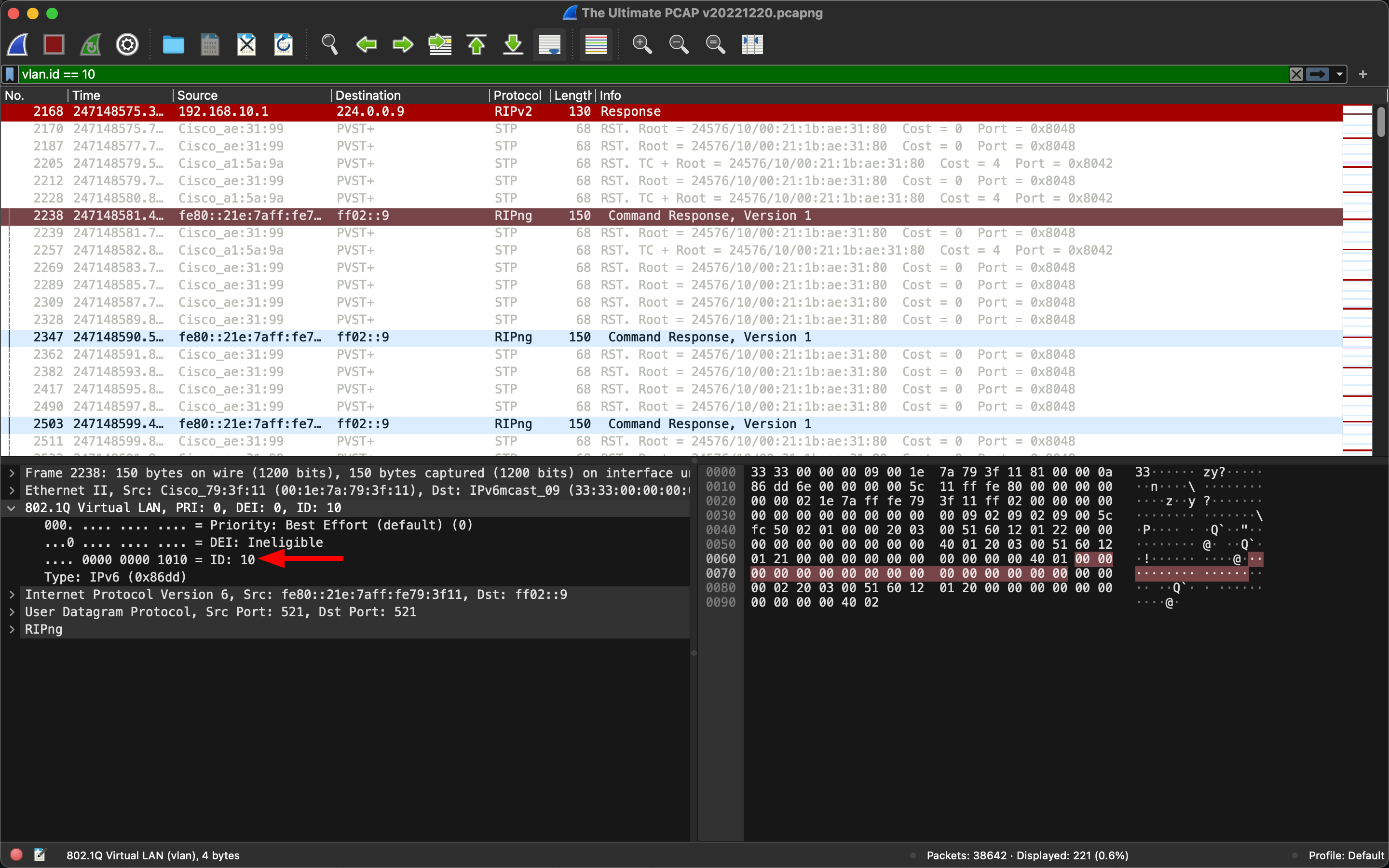
Additionally, to enumerate the used VLAN IDs from a packet dump, we can utilize tshark:
VLANs
VOIDstrike@htb[/htb]$ tshark -r "The Ultimate PCAP v20221220.pcapng" -T fields -e vlan.id | sort -n -u

1
2
3
7
10
20
30
40
50
60
70
80
90
121
125
224
Security Implications and VLAN Attacks
Regardless of improving a network’s security posture, adversaries can still circumvent the defensive mechanisms put forth by VLANs. Although in modern switched networks, the utilization of VLANs brings numerous advantages (such as simplified network maintenance and improved performance), it also introduces potential security risks, leading to various VLAN attacks. It is essential to grasp the underlying methodologies of these attacks and implement practical mitigation approaches to safeguard networks.
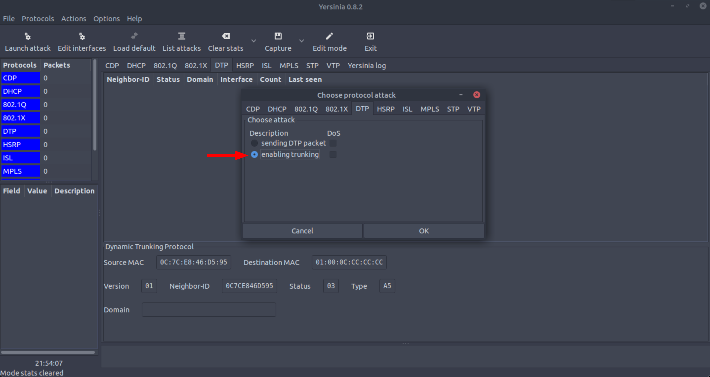
VLAN Hopping
VLAN hopping attacks enable traffic from one VLAN to be seen by another VLAN without the aid of a router. It exploits Cisco’s Dynamic Trunking Protocol (DTP), a protocol used to automatically negotiate the formation of a trunk link between two Cisco devices. An adversary needs to configure a host to mimic/act like a switch to take advantage of the automatic trunking port feature enabled by default on most switch ports. To exploit VLAN hopping, an adversary must be able to physically connect with a switch port that has DTP enabled. The adversary can abuse this connection by configuring a host connected to the switch on that specific port to spoof 802.1Q signaling and the DTP packets. If successful, the switch will eventually establish a trunk link with the adversary’s host, exposing the network packets, not only for a specific VLAN.
We can use tools such as Yersinia to perform VLAN hopping attacks:
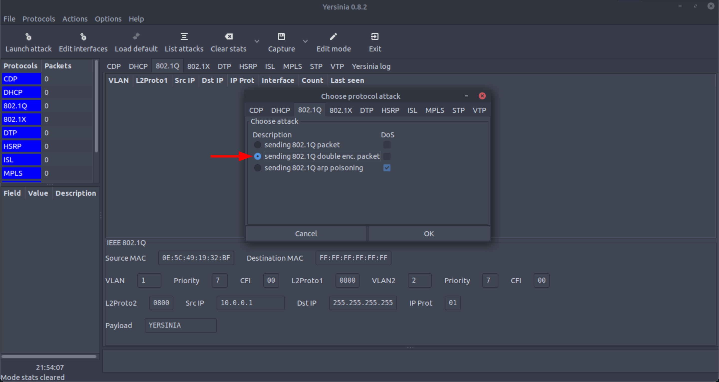
Double-tagging VLAN Hopping
The double-tagging VLAN hopping attack is an increasingly more sophisticated attack against VLANs. Although VLAN double-tagging is a legitimate practice that entities such as Internet Service Providers (ISPs) utilize (they can use their VLANs internally while carrying traffic from clients that are already VLAN tagged), adversaries can also attempt to abuse it. In a double-tagging VLAN hopping attack, an adversary embeds a hidden 802.1Q tag inside an Ethernet frame that already has an 802.1Q tag, allowing the frame to go to a different VLAN, which the original 802.1Q tag did not specify.
An adversary can carry out this attack following three steps. Bare in mind that this attack only works if the adversary is connected to a port residing in the same VLAN as the native VLAN of the trunk port:
- The adversary sends a
double-tagged 802.1QEthernetframe to the switch with the outer header having theVLANID of the adversary, which is the same as the nativeVLANof the trunk port. Assume that the nativeVLANisVLAN 10and thatVLAN 30is theVLANthe adversary wants to reach, where the victim resides. - The outer 4-byte
802.1Qtag arrives on the switch, and it is seen to be destined forVLAN 10, the nativeVLAN. After removing theVLAN 10tag, the frame is forwarded on allVLAN 10ports. On the trunk port, theVLAN 10tag is stripped (removed), and the packet is not re-tagged because it is part of the nativeVLAN. However, theVLAN 30tag is still intact (not stripped), and the first switch has not inspected it. - Subsequently, the switch will look only at the inner
802.1Qtag that the adversary sent, and it decides that the frame must be forwarded forVLAN 30, which is the adversary’s chosenVLAN. Now, the second switch will either send the frame to the victim port directly or flood it, depending on whether there is an existing MAC address table entry for the victim host.
Scapy allows carrying out the double-tagging VLAN hopping attack, in addition to Yersinia:
VXLAN
We mentioned previously that the VID field within the ‘802.1Q’ header inside an ‘Ethernet’ frame is only 12 bits, allowing for 4094 VLANs. While this number of VLANs might be sufficient for small networks, more is needed for data centers and cloud service providers, which require extensive segmentation. Additionally, current Layer 2 networks utilize the IEEE 802.1D Spanning Tree Protocol (STP) to prevent network loops caused by redundant paths. However, some data center operators encounter limitations with STP, such as link blocking, which reduces available ports and prevents resiliency through multipathing. These challenges hinder network efficiency in virtualized environments that rely on Layer 2 physical infrastructure. A critical requirement in such environments is the seamless scalability of the Layer 2 network across the entire data center and even between data centers to allocate computing, networking, and storage resources efficiently. Nevertheless, traditional approaches like STP, while ensuring a loop-free topology, can deactivate many links, further exacerbating the problem.
RFC7348 offers a solution to these problems and limitations in Layer 2 networks by introducing Virtual eXtensible Local Area Network (VXLAN), which is essentially a ‘Layer 2 overlay scheme on a Layer 3 network.’ VXLAN is specifically designed to address the limitations of traditional Layer 2 networks and cater to the requirements of Layer 2 and Layer 3 data center network infrastructures in a multi-tenant environment with virtual machines (VMs). Operating over the existing networking infrastructure, VXLAN provides an innovative way to seamlessly extend a Layer 2 network. Its primary objective is to facilitate the scaling of Layer 2 networks across expansive data center landscapes, even spanning multiple physical data locations. Each VXLAN overlay is termed a VXLAN segment, ensuring that only VMs within the same VXLAN segment can communicate with each other, thus maintaining network isolation and security. A 24-bit segment ID, known as the VXLAN Network Identifier (VNI), uniquely identifies each VXLAN segment. Adopting VXLAN allows for the coexistence of 16 million VXLAN segments within the same administrative domain, providing scalability and flexibility for modern data centers and virtualized environments.
Cisco Discovery Protocol
Cisco Discovery Protocol (CDP) is a layer-2 network protocol from Cisco that is used by Cisco devices such as routers, switches, and bridges to gather information about other directly connected Cisco devices. This information can be used to discover and track the network’s topology and help manage and troubleshoot the network. This protocol is usually enabled in Cisco devices, but it can be disabled if it is not needed or if it should be disabled for security reasons.
CDP Network Traffic
VLANs
22:14:11.563654 CDPv2, ttl: 180s, checksum: 0xebc1 (incorrect -> 0x8b71), length: 180
        Device-ID (0x01), length: 14 bytes: 'router.inlanefreight.loc'
        Addresses (0x02), length: 8 bytes:
                IPv4 (0x01), length: 4: 10.129.100.1
        Port-ID (0x03), length: 9 bytes: 'Ethernet0/0'
        Capability (0x04), length: 4: (0x00000010): Router
        Version String (0x05), length: 27 bytes: 'Cisco IOS Software, C880 Software'
        Platform (0x06), length: 26 bytes: 'Cisco 881 (MPC8300) processor'
The shown message contains information about the device itself, such as the device name, IP address, port name, and functionality of the router, as well as information about the operating system and hardware platform of the device. Besides, we can see in the first line from the CDPv2 that we are dealing with the Cisco Discovery Protocol.
For comparison, we can look at another protocol called Spanning Tree Protocol (STP). The STP is a network protocol that ensures no loops in a network with multiple connections between switches. There are no loops, and it prevents data packets from circulating in a loop and congesting the network.
STP Network Traffic
VLANs
22:14:11.563654 STP 802.1w, Rapid STP, Flags [Learn, Forward], bridge-id 8001.00:11:22:33:44:55.8000, length 43
        root-id 8001.AA:AA:AA:AA:AA:AA, cost 0, port-id 8001, message-age 0.00s, max-age 20.00s, hello-time 2.00s, forward-delay 15.00s
In this example, we see that an STP message was sent containing information about the root switch, the MAC address of the root switch, the ID of the port over which the message was sent, and other configuration parameters such as the maximum aging time, hello time, and forward delay.