Workflow
Networking Models
Two networking models describe the communication and transfer of data from one host to another, called ISO/OSI model and the TCP/IP model. This is a simplified representation of the so-called layers representing transferred Bits in readable contents for us.
The OSI Model
The OSI model, often referred to as ISO/OSI layer model, is a reference model that can be used to describe and define the communication between systems.
The term OSI stands for Open Systems Interconnection model, published by the International Telecommunication Union (ITU) and the International Organization for Standardization (ISO). Therefore, the OSI model is often referred to as the ISO/OSI layer model.
The goal in defining the ISO/OSI standard was to create a reference model that enables the communication of different technical systems via various devices and technologies and provides compatibility. The OSI model uses seven different layers, which are hierarchically based on each other to achieve this goal. These layers represent phases in the establishment of each connection through which the sent packets pass. In this way, the standard was created to trace how a connection is structured and established visually.
| Layer | Function |
|---|---|
7.Application | Among other things, this layer controls the input and output of data and provides the application functions. |
6.Presentation | The presentation layer’s task is to transfer the system-dependent presentation of data into a form independent of the application. |
5.Session | The session layer controls the logical connection between two systems and prevents, for example, connection breakdowns or other problems. |
4.Transport | Layer 4 is used for end-to-end control of the transferred data. The Transport Layer can detect and avoid congestion situations and segment data streams. |
3.Network | On the networking layer, connections are established in circuit-switched networks, and data packets are forwarded in packet-switched networks. Data is transmitted over the entire network from the sender to the receiver. |
2.Data Link | The central task of layer 2 is to enable reliable and error-free transmissions on the respective medium. For this purpose, the bitstreams from layer 1 are divided into blocks or frames. |
1.Physical | The transmission techniques used are, for example, electrical signals, optical signals, or electromagnetic waves. Through layer 1, the transmission takes place on wired or wireless transmission lines. |
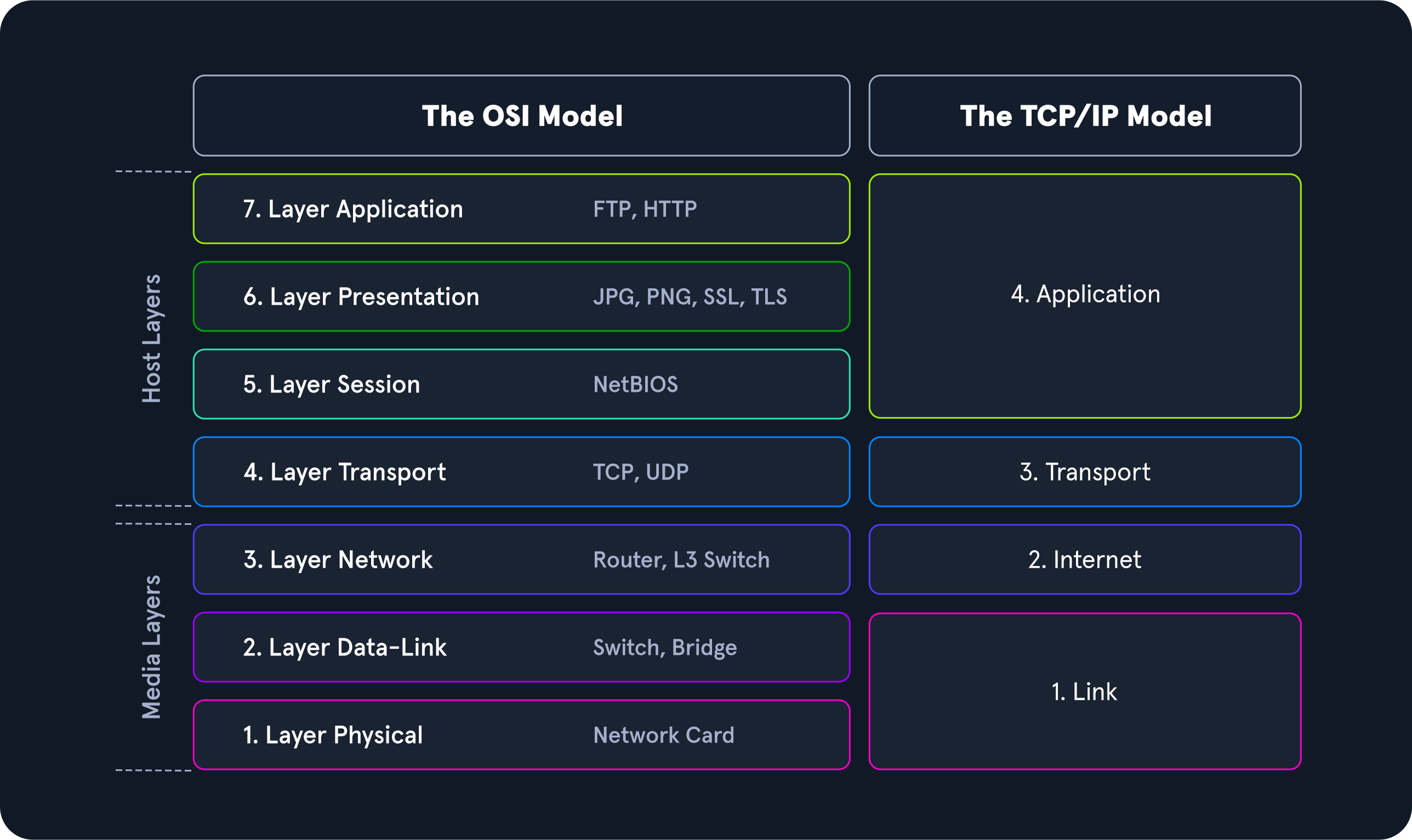
The layers 2-4 are transport oriented, and the layers 5-7 are application oriented layers. In each layer, precisely defined tasks are performed, and the interfaces to the neighboring layers are precisely described. Each layer offers services for use to the layer directly above it. To make these services available, the layer uses the services of the layer below it and performs the tasks of its layer.
If two systems communicate, all seven layers of the OSI model are run through at least twice, since both the sender and the receiver must take the layer model into account. When an application sends a packet to the other system, the system works the layers shown above from layer 7 down to layer 1, and the receiving system unpacks the received packet from layer 1 up to layer 7. Therefore, a large number of different tasks must be performed in the individual layers to ensure the communication’s security, reliability, and performance.
The TCP/IP Model
TCP/IP (Transmission Control Protocol/Internet Protocol) is a generic term for many network protocols. The protocols are responsible for the switching and transport of data packets on the Internet. The Internet is entirely based on the TCP/IP protocol family.
However, TCP/IP does not only refer to these two protocols but is usually used as a generic term for an entire protocol family. For example, ICMP (Internet Control Message Protocol) or UDP (User Datagram Protocol) belongs to the protocol family. The protocol family provides the necessary functions for transporting and switching data packets in a private or public network.
The TCP/IP model is also a layered reference model, often referred to as the Internet Protocol Suite. The term TCP/IP stands for the two protocols Transmission Control Protocol (TCP) and Internet Protocol (IP). IP is located within the network layer (Layer 3) and TCP is located within the transport layer (Layer 4) of the OSI layer model.
| Layer | Function |
|---|---|
4.Application | The Application Layer allows applications to access the other layers’ services and defines the protocols applications use to exchange data. |
3.Transport | The Transport Layer is responsible for providing (TCP) session and (UDP) datagram services for the Application Layer. |
2.Internet | The Internet Layer is responsible for host addressing, packaging, and routing functions. |
1.Link | The Link layer is responsible for placing the TCP/IP packets on the network medium and receiving corresponding packets from the network medium. TCP/IP is designed to work independently of the network access method, frame format, and medium. |
With TCP/IP, every application can transfer and exchange data over any network, and it does not matter where the receiver is located. IP ensures that the data packet reaches its destination, and TCP controls the data transfer and ensures the connection between data stream and application. The main difference between TCP/IP and OSI is the number of layers, some of which have been combined.
The most important tasks of TCP/IP are:
| Task | Protocol | Description |
|---|---|---|
Logical Addressing | IP | Due to many hosts in different networks, there is a need to structure the network topology and logical addressing. Within TCP/IP, IP takes over the logical addressing of networks and nodes. Data packets only reach the network where they are supposed to be. The methods to do so are network classes, subnetting, and CIDR. |
Routing | IP | For each data packet, the next node is determined in each node on the way from the sender to the receiver. This way, a data packet is routed to its receiver, even if its location is unknown to the sender. |
Error & Control Flow | TCP | The sender and receiver are frequently in touch with each other via a virtual connection. Therefore control messages are sent continuously to check if the connection is still established. |
Application Support | TCP | TCP and UDP ports form a software abstraction to distinguish specific applications and their communication links. |
Name Resolution | DNS | DNS provides name resolution through Fully Qualified Domain Names (FQDN) in IP addresses, enabling us to reach the desired host with the specified name on the internet. |
ISO/OSI vs. TCP/IP
TCP/IP is a communication protocol that allows hosts to connect to the Internet. It refers to the Transmission Control Protocol used in and by applications on the Internet. In contrast to OSI, it allows a lightening of the rules that must be followed, provided that general guidelines are followed.
OSI, on the other hand, is a communication gateway between the network and end-users. The OSI model is usually referred to as the reference model because it is newer and more widely used. It is also known for its strict protocol and limitations.
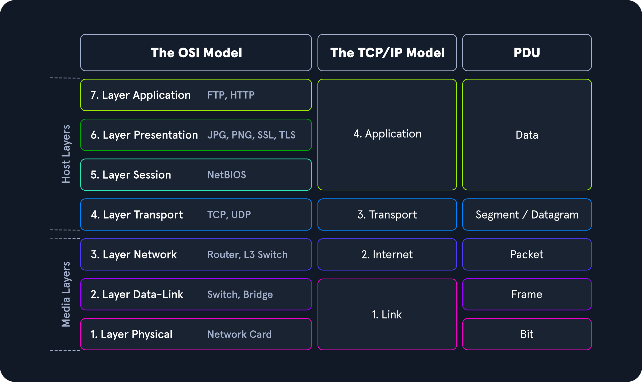
Packet Transfers
In a layered system, devices in a layer exchange data in a different format called a protocol data unit (PDU). For example, when we want to browse a website on the computer, the remote server software first passes the requested data to the application layer. It is processed layer by layer, each layer performing its assigned functions. The data is then transferred through the network’s physical layer until the destination server or another device receives it. The data is routed through the layers again, with each layer performing its assigned operations until the receiving software uses the data.
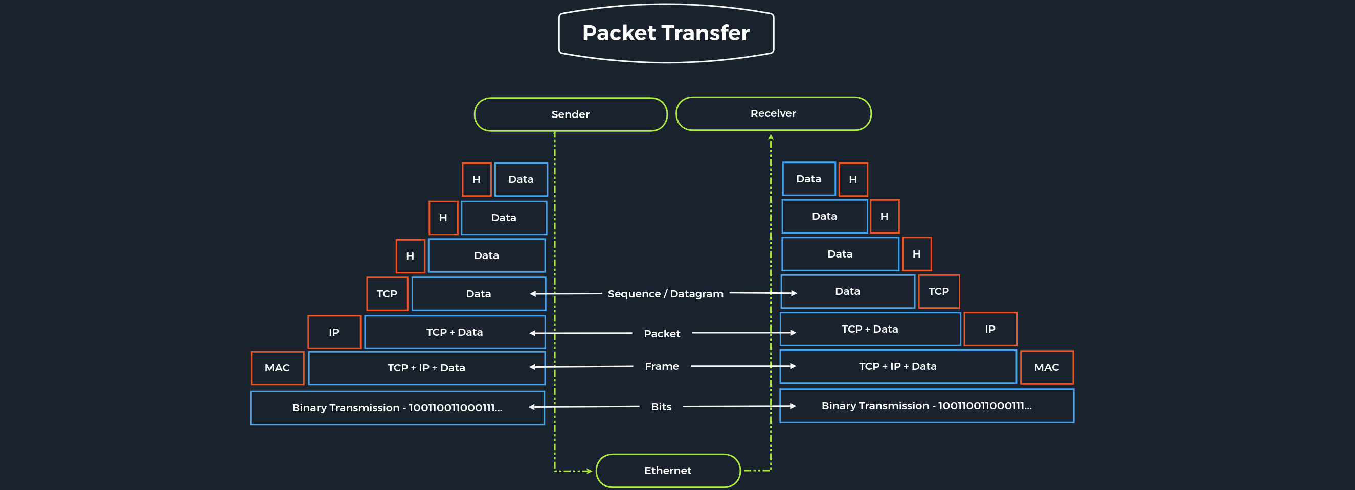
During the transmission, each layer adds a header to the PDU from the upper layer, which controls and identifies the packet. This process is called encapsulation. The header and the data together form the PDU for the next layer. The process continues to the Physical Layer or Network Layer, where the data is transmitted to the receiver. The receiver reverses the process and unpacks the data on each layer with the header information. After that, the application finally uses the data. This process continues until all data has been sent and received.
For us, as penetration testers, both reference models are useful. With TCP/IP, we can quickly understand how the entire connection is established, and with ISO, we can take it apart piece by piece and analyze it in detail. This often happens when we can listen to and intercept specific network traffic. We then have to analyze this traffic accordingly, going into more detail in the Network Traffic Analysis module. Therefore, we should familiarize ourselves with both reference models and understand and internalize them in the best possible way.